2002 dodge ram 1500 speedometer not working
There are several reasons why the speedometer does not move:
1. Failure with vehicle speed sensor and sensor drive mechanism causes the speedometer to be unable to move;
2. The speedometer itself fails;
3. The linear speed or mechanism connecting the sensor and the speedometer is faulty;
4. The trip computer is related. For vehicle models, the diagnostic apparatus can be used to detect and determine where the fault is. The indication of the speedometer depends on the speed sensor. The sensor is installed on the gearbox, and different pulse signals are obtained through different rotating speeds, and then converted into pointer output, which is the current speed seen. Regulations require that the speedometer display be slightly higher than the actual speed, which is for safety.
Read the fault code with the fault detector (WITECH), and find that the fault code "U0184-00 Lost Communication with Radio" is stored in the air conditioning control module (HVAC); The fault code "U0010-00 CAN internal bus" is stored in the body control module (BCM) and the radio amplifier (AMP); The fault code "U0147-00 lost communication with telematics gateway" is stored in the heated seat control module (HSM) and BCM. It is inferred that the vehicle has communication faults. Since the modules storing fault codes are on the CAN IHS bus, it is inferred that the communication of the CAN IHS bus is faulty. Disconnect the negative terminal of the battery, and use a multimeter to measure the resistance between DLC terminal 3 and terminal 11 (that is, the terminal resistance of CAN IHS bus), which is 61.7 Ω, normal. Measure the communication waveform on the CAN IHS bus with a pico oscilloscope (Fig. 2). It is found that the voltage on the CAN H line is pulled up from about 0.9 V to about 3.3 V (normally, it should be pulled up from about 2.5 V to about 3.5 V), and the voltage on the CAN L line is quickly pulled down from about 0.8 V to 0 V, and then pulled up to about 1.2 V (normally, it should be pulled down from about 2.5 V to about 1.5 V). This confirms that there is a fault in the communication of the CAN IHS bus.
Find the body star connector and disconnect the 2 terminal wire connector above in turn. When the wire connector C3 (connected to the driver's door control module) is disconnected, the communication waveform returns to normal. Remove the driver's side door trim panel. It is found that the vehicle is equipped with an automatic window lifting control module, which is connected to the CAN IHS bus through the communication line on the driver's side door control module.
 English
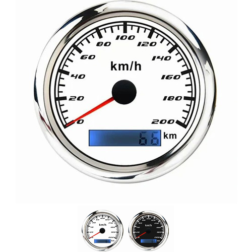
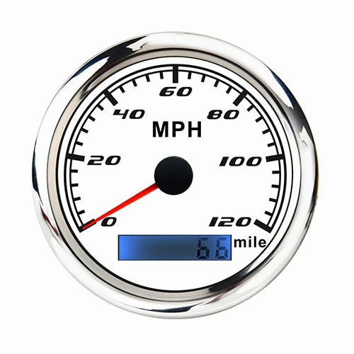
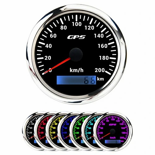
Get a Quote / Info