 English
 autogage tachometer wiring diagram
Wiring the autogauge tachometer , add a DC motor to the main shaft of the engine (e.g. next to the generator) . Then measure the voltage and calibrate the corresponding value with the autogauge tachometer to make the scale .
When disassembling the combination instrument, remove the negative battery cable first to avoid short circuit when touching the back of the instrument panel . When removing the combination instrument trim panel , since the fixing screws are generally hidden , it is necessary to carefully look for the fixing screws , otherwise forcible removal will damage the trim panel . When disassembling the instrument and sensor , be careful not to knock . The wiring between the instrument and the sensor and the grounding of the sensor must be reliable . The terminals of electromagnetic instruments have different polarity and shall not be connected incorrectly .
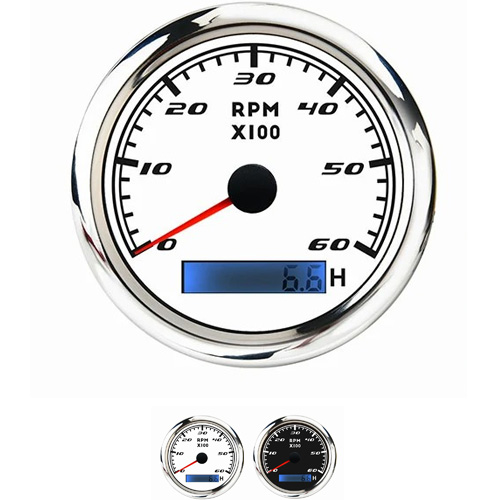
The faster the speed, the more pulses will be generated, and the larger the value will be at this time. The working principle of the autogauge tachometer is actually a speed sensor on the engine . When our engine starts to work , this signal will be transmitted to the brain of our car through the chopper , and finally converted into an electrical signal , which will be reflected on our speed dashboard .
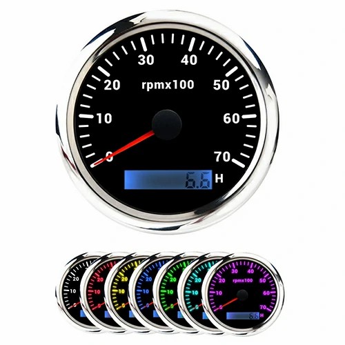
Autogauge diesel engine . The three terminals on the generator are W, B+, D+, D . The tachometer of autogauge is wired to the generator The generator w terminal is the sensing output of the auto gauge autogauge tachometer .
B +: positive output terminal, which is connected to the positive pole of the battery and the electrical appliance (load) on the vehicle. The battery free motor b+ is directly connected to the air conditioner.
D +: three small power field diode terminals to provide continuous excitation current for the rotor.
E: Ground strap.
W: Phase output terminal, the output voltage is half of B + output voltage, and can be connected to autogauge tachometer, AC relay or DC relay.
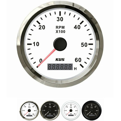
Engine autogauge tachometer is used to display the running speed of the engine in real time. Type: mechanical type and electronic type. Electronic type is widely used. Signal acquisition method: acquire pulse voltage signal from ignition system (usually adopted by gasoline engine). Obtain the speed signal from the engine speed sensor; Obtain the speed signal from the generator. Circuit: as shown in the following figure.

Get a Quote / Info