 English
 how a tachometer works
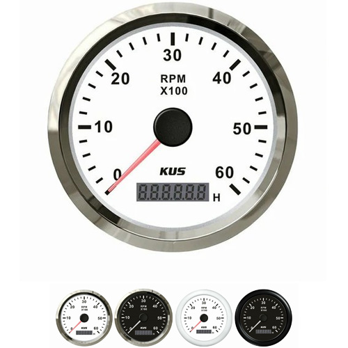
Automobile tachometer is generally pointer instrument, and a few of them are digital. The unit of measurement symbol is R / min, and the unit name is rpm. The range of the tachometer reflects the speed range of the engine. The part with white scale is the safe speed range, and the part with red scale is the dangerous speed range. In order to make better use of the vehicles, some performance vehicles and diesel vehicles also marked the green area on the tachometer, which is the most economical use area of the engine.
There is a crankshaft speed sensor on the engine, which rotates with the engine crankshaft, A pulse signal will be sent (some gasoline engines take the ignition pulse signal). This signal will be transmitted to the engine computer. After calculation, a control signal will be output and transmitted to the tachometer to control the rotation of the driving stepping motor on the tachometer (the pointer is directly installed on the rotating shaft of the stepper motor). The faster the engine speed is, the more pulses are generated, and the greater the speed value displayed on the table. In order to accurately display the speed, the stepper motor moves only 1 / 3 degree in one step.
Method of tachometer measurement
1. F / V conversion
Electronic speed measuring instrument, By speed sensor and meter (display) composition. At present, most of the commonly used speed sensors output pulse signals, which can be matched with the voltage and current input pointer meter and digital meter through frequency current conversion, or directly sent to PLC; the methods of frequency current conversion include resistance capacitance integration method, charge pump method and special integrated circuit method. Special integrated circuit Most of them are the synthesis of resistance capacitance integration method and charge pump method. At present, the commonly used special integrated circuits include LM331, ad654 and vf32, and the conversion accuracy is more than 0.1%; But at low frequencies, this conversion is powerless. Single chip microcomputer or FPGA is used for F / D and D / a conversion. The conversion accuracy is between 0.5 ~ 0.05%, the range is from 0 ~ 2Hz to 0 ~ 20kHz, and the reflection time becomes longer when the frequency is lower than 10Hz. For F / V conversion, please refer to the corresponding chip introduction and application materials, which will not be repeated in this paper.
2. Frequency operation
When there are certain requirements on display accuracy, reliability, cost and flexibility, the pulse frequency operation tachometer can be directly used. Frequency operation methods include fixed time counting method, fixed number timing method and synchronous counting timing method. The timing counting method has an error of ± 1 in measurement, and the error is large at low speed; the timing method (cycle measurement method) also has an error of ± 1 time unit, and the error is also large at high speed. Synchronous counting and timing method combines the advantages of the above two methods and achieves high accuracy in the whole measurement range. This method is basically used for more than 5 / 10000 measuring speed instruments.
Get a Quote / Info