 English
 what controls voltage gauge on my 1997 chevy truck
About the 1997 chevy truck , when the car is on fire, because the car is single wire system, only the positive line of the power supply will not be displayed by the voltmeter after it is burned and short circuited.
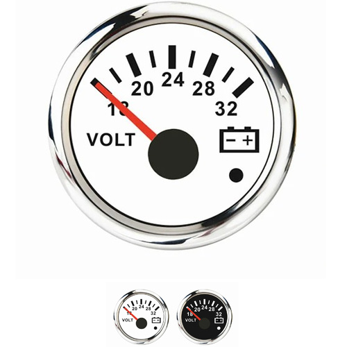
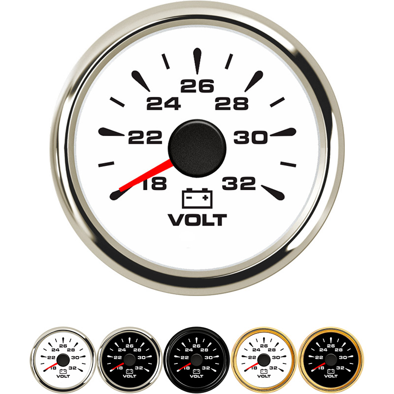
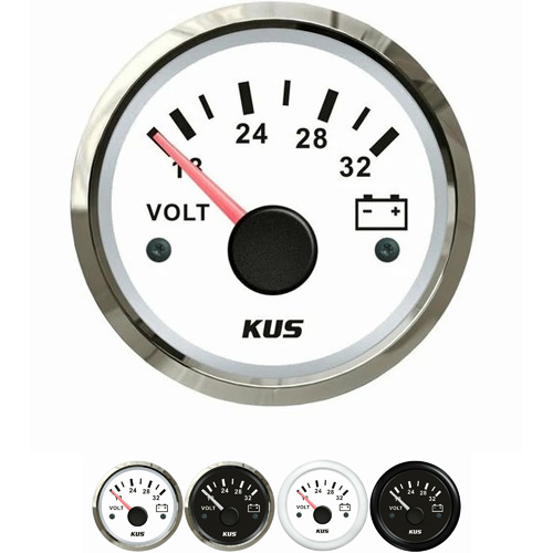
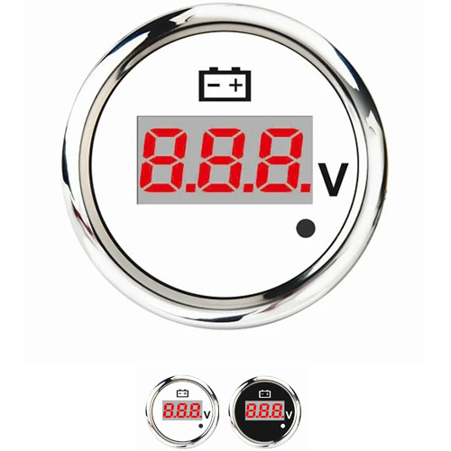
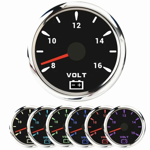
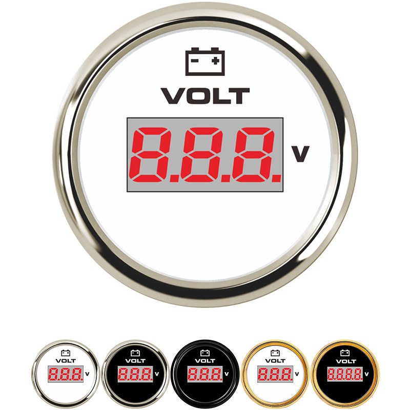
Check the battery power indicator: when the battery power indicator displays green, it indicates that the battery is full and the battery is intact. When the battery power indicator displays black, it indicates that the battery is low and needs to be charged. When the battery power indicator displays colorless or light yellow, it indicates that the battery is basically used up.
The generator is connected in parallel with the battery, and the negative pole of the battery must be grounded. The positive pole of the battery is connected to the positive pole of the motor through the ammeter (or directly). When the generator works, the normal voltage is 0.3 ~ 3.5V higher than the voltage of the battery. This is mainly to overcome the line voltage drop and make the battery sufficient when charging, so as not to overcharge.
The voltmeter is connected in parallel with the ignition switch and displays the system voltage only when the ignition switch is on. 12V system often uses 10V ~ 18V, 24V system often uses 20 ~ 36V voltmeter.
Wiring law of electronic control system:
1. Understand the function of the electronic control system, which components are controlled and which physical quantities are controlled. For example, some control ignition, some control fuel injection, and some control voltage gauge.
2. Master the name, installation position, function, structural principle and main technical parameters of each sensor. For example: the resistance value in the power-off state, the potential and current in the power-on state, and find out whether the signal voltage of various sensors is analog quantity, pulse quantity or switching quantity.
3. Master the name, installation position, function, structural principle and main parameters of various actuators.
4. Understand the functions of the main function blocks inside the computer, and master the serial number, letter code and normal voltage or resistance between the terminals of each sensor and actuator.
5. Understand the installation position of computers, sensors and actuators on the vehicle, distinguish the serial number and code of connectors and their terminals, and distinguish the shape and characteristics of components.
6. Understand the fault diagnosis socket or tester communication interface, find the fault code table of each vehicle according to the country, manufacturer and vehicle dispatch, read the fault code with the flash of the instrument or fault inspection lamp, determine the fault location and eliminate the fault.
Get a Quote / Info