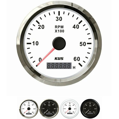
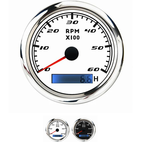
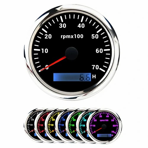
diesel tachometer wiring diagram
Now we introduce the circuit principles of two electronic tachometers for gasoline engines.
1. Capacitance discharge tachometer
The capacitance discharge tachometer is shown in the figure, which is the circuit schematic diagram of the tachometer taken from the ignition system of Santana car. Principle: when the primary circuit is on, the triode VT is cut off and the capacitor C2 is charged. The charging current is from the positive pole of the battery → ignition switch → resistance R3 → capacitor C2 → diode VD2 → negative pole of the battery. When the primary circuit is cut off, the triode VT is turned on, the capacitor C2 is discharged, and the discharge current passes through the triode vt → ammeter → diode VD1. When the engine is working, the primary circuit of the ignition system is constantly on and off, and the capacitor C2 is constantly charged and discharged. Because the number of times the primary circuit is turned on and off is directly proportional to the engine speed, the average value of current in the ammeter is directly proportional to the engine speed, so the engine speed can be calibrated with the average value of current.

2. Monostable trigger tachometer
The principle of monostable trigger tachometer is shown in Figure 6-20. When the contact K of the primary circuit of the ignition system is disconnected, the base of VT1 gets a positive pulse signal, VT1 is on, tachometer n passes through a certain current, when VT is on, the negative jump signal of the collector is coupled to the base of vt2 through capacitor C1 to cut off vt2, and the positive jump voltage of the collector is coupled to the base of VT1 through R9 to further turn on VT1. The time to keep VT1 on is determined by the time required for the power supply to charge C1 to the specified voltage value through resistors R7, R6 and R10. When the charging voltage on C1 rises to the on voltage of vt2, vt2 turns on and couples the negative jump signal of vt2 collector to the base of VT1 through R9, then VT1 is cut off and the circuit returns to the original state. When the engine is working, the contact K is opened and closed periodically, and the average value of a series of square wave pulse currents passing through the tachometer is directly proportional to the speed of the engine. The transient steady-state time of VT1 on and vt2 off shall be able to prevent the influence of spark discharge high-frequency electromagnetic oscillation signal and avoid mistriggering the speed circuit, resulting in measurement error.

After understanding the principle, you can wire the diesel tachometer. Install a tachometer sensor on the flywheel housing and connect two wires to the tachometer. (two lines are different)
 English


Get a Quote / Info