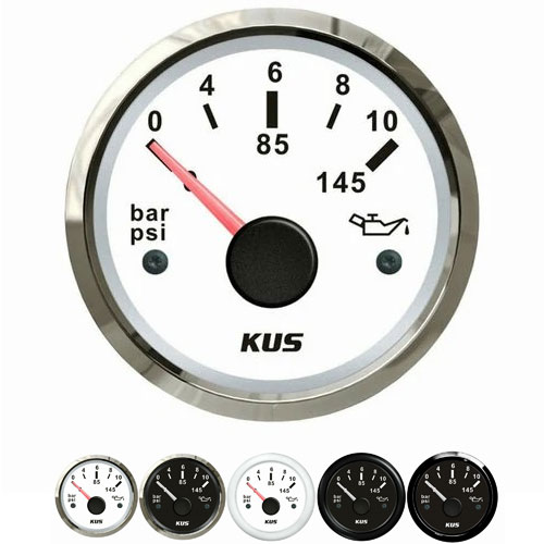
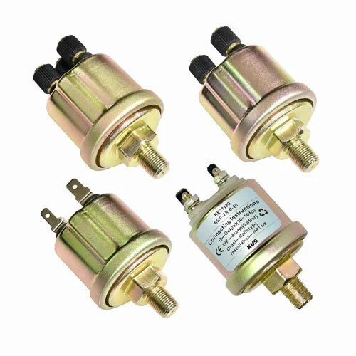
motorcycle oil pressure gauge kit
The use steps of motorcycle oil pressure gauge kit:
1. Press down the gasoline plug into the engine oil pan and insert it into the sensor port of the gasoline pressure gauge.
2. Turn on the gasoline pump and observe whether the reading on the indicator is within the normal range.
3. If the reading is out of the normal range, pull out the gasoline pressure gauge and check whether the connection joint of the gasoline pressure gauge is loose to ensure the connection performance.
4. Reinstall the gasoline pressure gauge, and observe again whether the reading on the indicator is within the normal range. The method of using the motorcycle gasoline pressure gauge is very simple. First, connect the test gauge to the engine of the motorcycle, and put the probe into the gasoline tank. Then, turn on the power correctly according to the instructions, and the pointer will point to the scale on the pressure gauge. Under normal circumstances, the normal working pressure is between 0.3 bar and 1.2 bar. If the pressure is lower than 0.3 bar or exceeds 1.2 bar, it means that there may be problems that need to be checked and repaired in time.
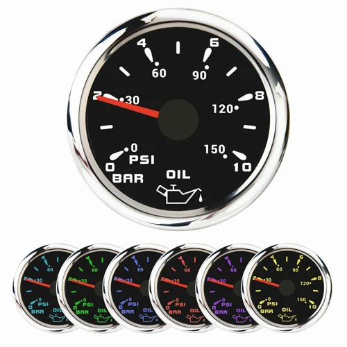
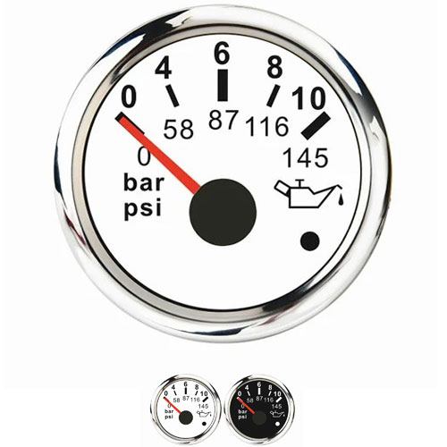
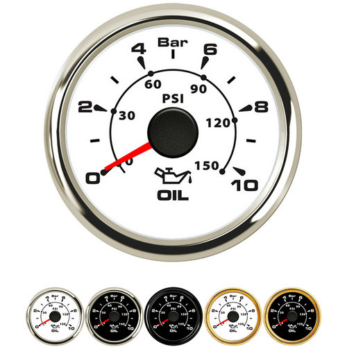
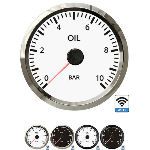
The engine oil pressure indicating gauge is installed on the instrument panel, and the engine oil pressure sensor is installed on the main oil channel of the engine or the oil filter, and the two are connected by wires. Commonly used oil pressure gauges include bimetallic oil pressure gauges, bimetallic oil pressure sensors, electromagnetic oil pressure gauges, and resistive oil pressure sensors. Bimetallic oil pressure gauges are widely used. The graduation numbers and symbols of the pressure gauge dial shall be complete and clear. The graduation scales on the dial should be evenly distributed, and the enclosed central angle is generally 270°. The pointer of the pressure gauge should extend into all the graduation lines, and the width of the pointer indication end should not be greater than 1/5 of the minimum graduation interval. The distance between the pointer and the plane of the indexing plate should be within the range of 1~3mm. For the case with an outer diameter of more than 200mm (including 200mm), the distance between the pointer and the plane of the indexing plate should be within the range of 2~4mm.
 English
Get a Quote / Info