 English
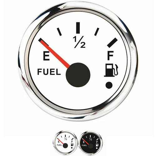
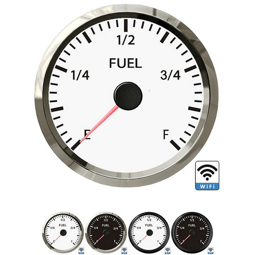
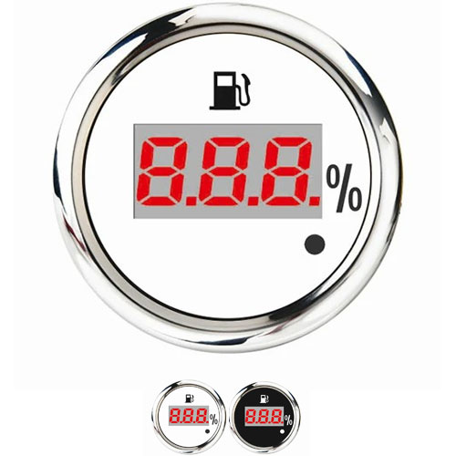
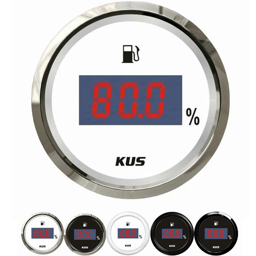
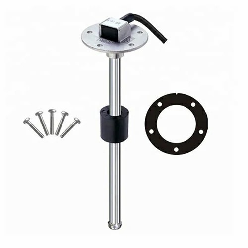
 yamaha auxiliary fuel tank level gauge
1. Determine medium density
The medium density can be measured with a standard densimeter or checked according to the specific information provided by the user. The medium density needs to be recorded and filed to ensure that the medium density can meet the requirements of the Level sensor instruction manual. Although the medium density has influence on the indication of Level sensor in theory, the zero and full value of Level sensor can be directly adjusted through potentiometer in actual use.
2. Determine the reference zero point
Use a Vernier scale to measure the inner diameter D of the connecting pipe, and determine a lower ruler point of the standard liquid level on the upper part of the tank. If possible, it is better to grind it into a groove to avoid the swing of the depth gauge, and make a mark; Inject water into the tank manually without pressure in the tank. When the water level is slightly higher than the water inlet pipe of the Level sensor, stop injecting water. Open the manual ball valve E at the lower connecting flange port and loosen the connecting flange F between the tank body and the calibrated Level sensor (do not remove it, so that the water flow will not rush). When there is no surging flow in the pipeline, close E, remove the flange, open E when the liquid in the tank is stable, and then wait for the trickle state, Stable for 1 minute (drainage valve can be used if necessary to improve detection efficiency);
3. Use a sounding steel tape to measure the distance ha from the measuring point to the water surface. The actual null height h 0=ha-D/2. This state is the calibration of each liquid level point at the measurement zero point of the Level sensor
4. Install the flange, close E, and continue to inject water into the tank until the main scale indicating the need to calibrate the liquid level on the flip plate is reached. After the water surface stabilizes, measure the output current Ii and the water level height hi. The actual liquid level is: H0=h0 hi=ha-D/2 hi; Continue measuring at other points until full scale is reached. Calibration of liquid level zero and full
5. While determining the reference zero point, adjust the zero point Potentiometer so that the output electrical signal is displayed as 4mA; The full scale adjustment is carried out at the upper limit of the standard liquid level, and the full scale Potentiometer is adjusted to make the output electrical signal display 20mA. If there is a deviation in the output during the down stroke measurement, refer to this method for adjustment. On site calibration requires repeating the above steps for three return measurements.

Get a Quote / Info