 English
 auto meter voltage gauge wiring
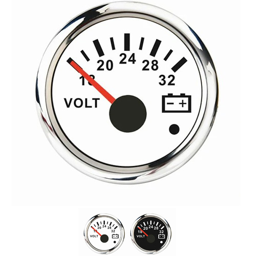
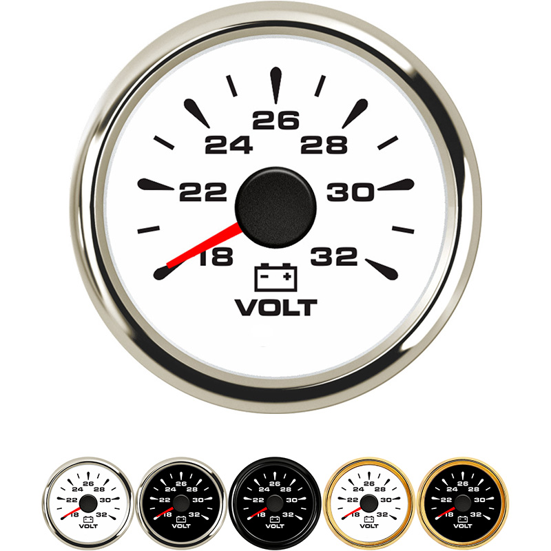
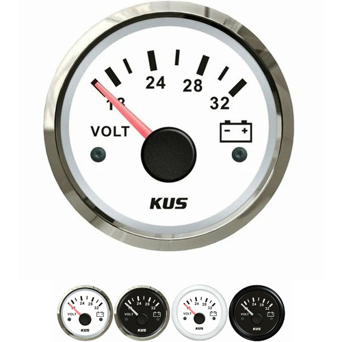
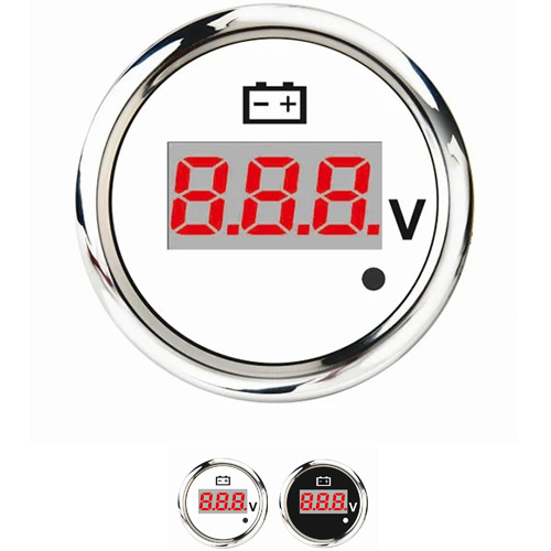
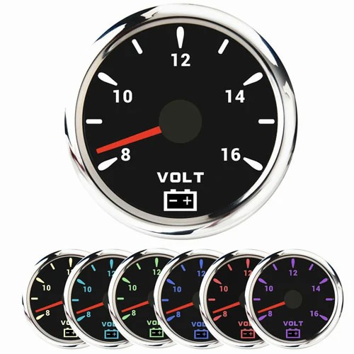
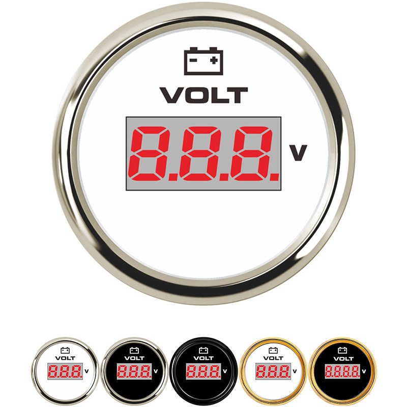
Our company provide different size auto meter, include 52mm or 85mm. Today we introduce our 2" 52mm auto meter voltage gauge LED needle/digital display Blu ray racing truck modified vehicle, including installation accessories 12V 0.3A.
About the auto meter voltage gauge wiring, firstly we need to know it clearly. Th gauge gower supply: DC (10-15v) 12V general. The current: ign Max 0.3A ILM 0.3A and the reading: 15V.The warning voltage is lower than 11.5V (red light). It has racing appearance and experience, advanced and lightweight products. Also , we provide fixing and installation accessories together with the gauge.
About the installation, it is easy. It is with English version of operation manual and professional installation recommendations attached. Let us list the wiring steps:
1. The instrument can be installed in a hole with a diameter of 2 "(52mm) or on the fixed installation panel of automobile instrument, with a fixed installation frame attached.
2. First drill about 3 / 8 "(9.5mm) holes, and then install the rubber lock ring, so that the pressure or vacuum line can pass through the sheet metal parts, like a firewall.
3. Install the additional nylon pressure line behind the instrument, connect the adapter and ferrule, tighten the nut, and connect the transmission line to the engine room through the rubber lock ring. The pressure gauge is connected to the engine pressure port and fixed by 1 / 8 "(3.2mm) connector and pressure nut, and the vacuum gauge is installed and fixed by 1 / 8" (3.2mm) connector.
4. Start the engine and comprehensively check the sealing degree of installation and whether there is leakage.
5. Screw on the light interface end of the instrument, connect the yellow wire to the light circuit port or 12VDC power port, and connect the black wire to a good grounding.
The lines of each color should correspond well.
1. Red (black) - the positive pole of the power supply, which is led out by adding a fuse in front of the relay and connected to the switch of the control box.
2. White (green) -- the control box switch is connected to the relay control input, and the relay control output is connected to the negative pole behind the shunt.
3. Yellow - the positive pole of the rear power supply of the relay is led out, and the positive pole of the voltmeter and ammeter is fused.
4. Green (white) - connect the red line of ammeter and the black line of voltmeter, and connect the negative pole in front of the shunt.
5. Black - (red) is connected to the ammeter, and the black wire is connected to the negative pole behind the shunt.
Get a Quote / Info