how to wire a tachometer to electronic ignition
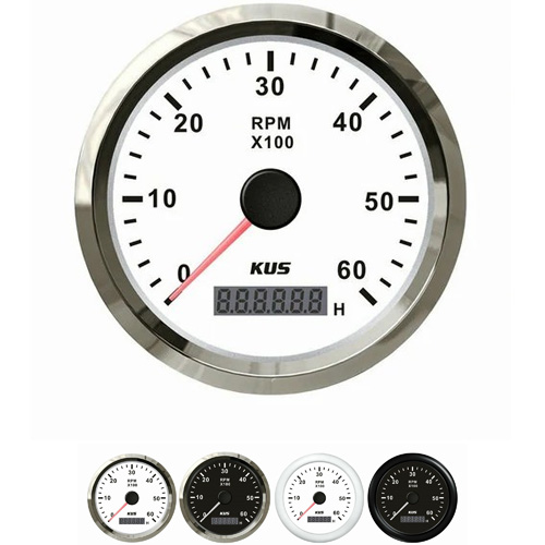
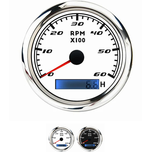
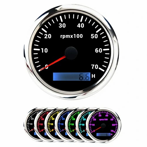
The connection diagram of the tachometer and ignition is to add a DC motor to the main shaft of the engine (such as next to the generator). Then measure its voltage and calibrate the corresponding value with a tachometer to make a scale. For motorcycles, the wiring is very simple, with only four leads: red, black, yellow, and green. The power line of the tachometer must be connected to the power fuse at all times, as the clock of the tachometer needs to work continuously. 2. The black wire, the ground wire of the tachometer, can be connected to any ground wire. 3. The yellow line is the working line of the tachometer. After the yellow line is powered on, all parts of the tachometer begin to work, and the light on the panel is turned off. The yellow wire is connected to the power cord behind the ignition key switch. After turning on the key switch, the tachometer begins to operate. 4. The green wire, the signal wire of the tachometer, is connected to the trigger signal terminal of the igniter.
The electronic version connects the tachometer and igniter to the high-voltage package through a speed measuring wire (wire). However, depending on the vehicle model, some speed measuring wires are also connected to other places, depending on the specific situation.
Add a DC motor to the main shaft of the engine (such as next to the generator). Then measure its voltage and calibrate the corresponding value with a tachometer to make a scale. For motorcycles, the wiring is very simple, with only four leads: red, black, and yellow green. The red line is the power cord of the tachometer. As the clock of the tachometer needs to work continuously, the red line must always be powered and can be connected behind the power fuse. 2. The black wire, the ground wire of the tachometer, can be connected to any ground wire. 3. The yellow line is the working line of the tachometer. After the yellow line is powered on, all parts of the tachometer begin to work, and the light on the panel is turned off. The yellow wire is connected to the power cord behind the ignition key switch. After turning on the key switch, the tachometer begins to operate. 4. The green wire, the signal wire of the tachometer, is connected to the trigger signal terminal of the igniter.
 English


Get a Quote / Info