 English
 johnson outboard tachometer wiring
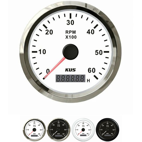
The wiring method for the johnson outboard engine marine tachometer x100r/min should include a DC motor on the main shaft of the engine (such as next to the generator). Then measure its voltage and calibrate the corresponding value with a tachometer to make a scale. For motorcycles, the wiring is very simple, with only four leads: red, black, yellow, and green.
1. The red line is the power cord of the tachometer. As the clock of the tachometer needs to work continuously, the red line must always be powered and can be connected behind the power fuse.
2. The black wire, the ground wire of the tachometer, can be connected to any ground wire.
3. The yellow line is the working line of the tachometer. After the yellow line is powered on, all parts of the tachometer begin to work, and the lights on the panel light up. The yellow wire is connected to the power cord behind the ignition key switch. After turning on the key switch, the tachometer begins to operate.
4. The green wire, the signal wire of the tachometer, is connected to the trigger signal terminal of the igniter.
The wiring method for the tachometer wire of the johnson outboard engine is as follows: connect the tachometer wire to the speed sensor of the outboard engine, then connect the other end to the controller of the outboard engine, and finally connect the controller to the power supply of the outboard engine. In addition, when wiring, attention should be paid to the correctness of the wiring to avoid damage to the external machinery.
Regarding the tachometer sensor of the johnson outboard engine, two wires are connected to the tachometer. (The two lines are different). Engine speed sensor: It is basically installed on the front pulley of the engine and senses with the sensing device of the engine body. The specific working principle is a pulse wave, which sends a signal every time it is induced. The sensor of the body is pulled to the tachometer, and the specific speed value is calculated based on the obtained pulse wave time difference.
Precautions for speed sensors: 1. The metal shielding layer in the sensor output line should be connected to the ground zero line. 2. It is not allowed to use or place in strong magnetic field environments with temperatures above 25 ℃. 3. During installation and transportation, strong impacts should be avoided. 4. When the measured shaft has a large runout, attention should be paid to enlarging the gap appropriately to avoid damage. 5. In order to consider using the sensor in harsh environments, it is sealed immediately after assembly and debugging, so it cannot be repaired.
Get a Quote / Info