 English
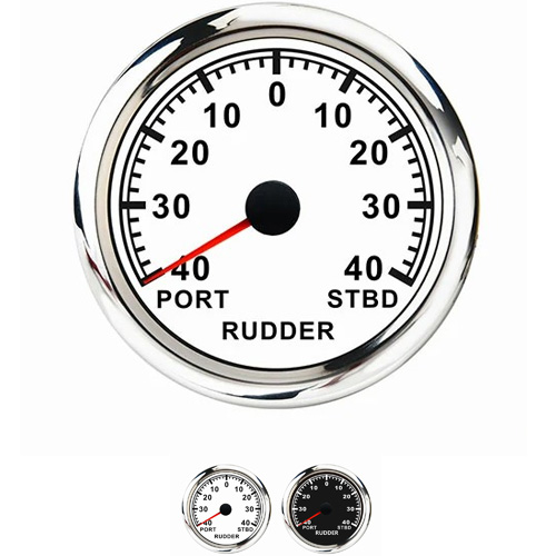
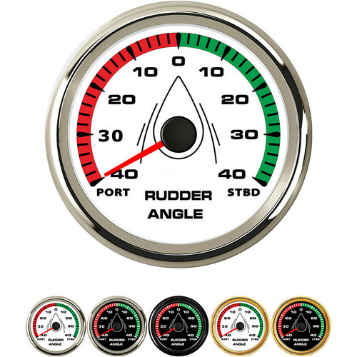
 rudder angle indicator installation instructions
The four wires of rudder angle indicator installation instructions as follows: 1. The cab and its four rudder angle meters have the dimming function. The two wing rudder angle meters have their own dimming devices, and the two rudder angle meters' dimming potentiometer in the cab are connected according to the voltage division connection. 2. Before powering on and debugging, remove all the wiring terminals of the rudder angle meter, measure and confirm the DC24V power line and rudder angle signal line, connect the DV24V power line, and keep the rudder angle signal line temporarily suspended.
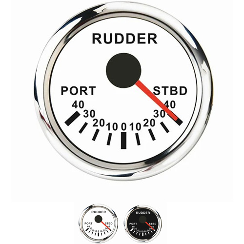
Inconsistent adjustment of rudder angle indicator and meter: rudder angle indicator does not rotate: check power supply and fuse. Jumping when the rudder angle indicator rotates: Check if the clearance between the rudder angle transmitter gears is too large.
Firstly, when steering, one should pay attention to energy and carefully listen to and respond to the steering instructions. When turning the rudder, one should look at the bow of the ship, the compass, and the rudder angle indicator. When turning the rudder, the speed of turning the rudder should be fast. It is necessary to return to the rudder in advance and press the rudder in advance. The reaction should be fast because the ship has a large inertia and is floating on the water, and the resistance on the smooth surface of the water is small.
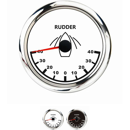
According to the position of rudder stock axis close to the width of rudder blade, it can be divided into ordinary rudder, balanced rudder and semi balanced rudder. Common rudder is also called unbalanced rudder. The rudder area of this type of rudder is all located behind the axis of the rudder stock. When turning the rudder, the center of the rudder pressure action is far from the axis of the rudder stock, so a rudder with a large output power is required to provide sufficient turning torque. The support points of non balanced rudder can be divided into two types: single pin type and multi pin type, of which the multi pin type is easy to ensure the structural strength.
Part of the rudder area of balanced rudder balanced rudder is located in front of the rudder stock axis, and the height of the entire rudder is evenly distributed. When turning the rudder, the center of rudder pressure action is closer to the rudder stock, so the required rudder output power is significantly less than that of the non balanced rudder.
Get a Quote / Info