 English
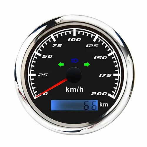
 speedometer sensor wiring diagram
There are two methods for measuring the three wires of the meter sensor. Method 1: Remove the connecting plug of the vehicle speed sensor, and check the resistance of the two leads of the sensor with the multimeter resistance gear. Method 2: Rotate the output shaft of the transmission, and use an automobile oscilloscope to detect the signal voltage waveform between the two leads of the vehicle speed sensor, which is an alternating current waveform. The amplitude and frequency of the waveform increase with the speed of the output shaft, which indicates that the sensor has good performance. Odometer sensors can be divided into magnetoelectric, Hall type and photoelectric type according to their types. The common type is Hall type, which generally has three lines, namely, power line VCC, signal line Vout and ground line GND. The colors are red, yellow/orange and black respectively. The red power line is connected to the power supply, the yellow signal line is connected to the instrument, and the black ground wire is grounded, which can be connected according to the color.
The odometer sensor is used to detect the rotational speed of the electronically controlled automobile tire, and transmit the detected signal to the ECU, so as to control the shift and cruise control of the automatic transmission. Its principle is to sense the number of turns of the tire through the sensors on the differential or axle shaft. Because the angular speeds of the axle shaft and the wheel are equal, the radius of the tire is known, and the mileage is directly calculated through mileage parameters.
Extended data:
In the past, automotive sensors were only used on engines, and have been extended to chassis, body and lighting electrical systems.
Types:
1. Intake pressure sensor: it reflects the change of the absolute pressure in the intake manifold and is the reference signal for ECU (engine electronic control unit) to calculate the fuel injection duration;
2. Air flow meter: measure the amount of air inhaled by the engine and provide it to ECU as the reference signal of fuel injection time;
3. Throttle position sensor: measures the opening angle of the throttle valve and provides it to ECU as the reference signal for fuel cut-off, fuel/air ratio control and ignition advance angle correction;
4. Crankshaft position sensor: detects crankshaft and engine speed and provides it to ECU as the reference signal for determining ignition timing and working sequence;
5. Oxygen sensor: detects the oxygen concentration in the exhaust gas and provides it to ECU as a reference signal to control the fuel/air ratio near the optimal value (theoretical value);
Get a Quote / Info