 English
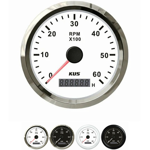
 analog tachometer for small small engine
The analog Tachometer works according to the magnetic principle. The faster the small engine speed, the more pulses the ignition coil generates, and the higher the speed value displayed on the meter. The unit of Tachometer is 1/min1000. There is a crankshaft speed sensor on the small engine, which sends out pulse signals as the small engine crankshaft rotates (some gasoline small engines take ignition pulse signals). This signal is transmitted to the small engine computer, and after calculation, a control signal is output and transmitted to the Tachometer to control the rotation of the drive stepper motor on the Tachometer.
The analog Tachometer is the schematic diagram of a pulse type electronic Tachometer that uses capacitors to charge and discharge. When the small engine is working, the contact of the Distributor keeps opening and closing, and its opening and closing times are proportional to the small engine speed, that is, every revolution of the crankshaft, the four stroke four cylinder small engine contacts open and close twice; The contacts of the six cylinder small engine are opened and closed three times, and intermittent current is generated by opening and closing the contacts. It is reshaped by the integration circuits R1, R2, and C1 and sent to the transistor VT1 to obtain a rectangular current with a fixed amplitude (current value) and pulse width (time). This current is measured in milliampere meter mA. When the contact is closed, the transistor VT1 is in a cut-off state without bias voltage, and the capacitor C2 is charged. The charging circuit is composed of a path of battery positive pole, resistor R3, capacitor C2, diode VD2, and battery negative pole. When the contacts are separated, the base potential of the transistor VT1 approaches the positive pole of the power supply, and VT1 switches from cut-off to conduction. At this time, the charge filled by capacitor C2 is discharged through a milliammeter, and the discharge circuit is from the positive pole of capacitor C2 to the transistor VT1 milliammeter diode VD2, and then back to the negative pole of C2. Repeat the process by repeatedly opening and closing the contacts. Diode VD2 provides a charging circuit for container C2, while VD1 provides a discharge circuit for C2. Due to the fact that the charge and discharge quantity Q of C2 is directly proportional to the capacitance C and the voltage U at both ends of the capacitor, i.e. Q=CU, the average discharge current within each cycle (T) is: I=Q/T=CU/T=CUf, where f - is the opening and closing frequency of the contact.
Get a Quote / Info