 English
 autometer fuel level gauge install
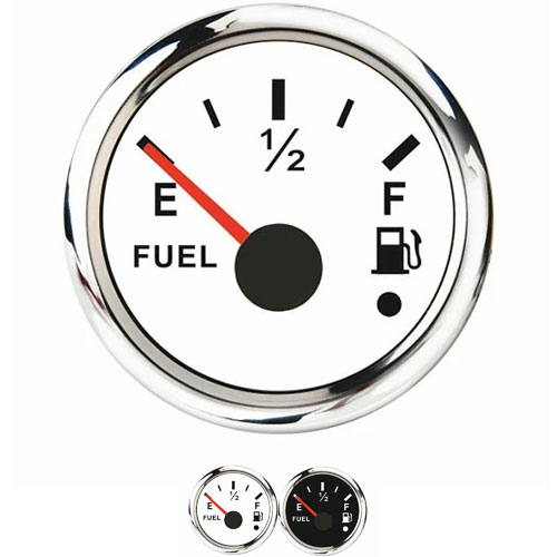
The fuel indicator system (usually mounted on the instrument panel) calculates and displays the amount of current passing through the transmission system. Once the amount of fuel increases, the optimal current passes through, and the meter reading (f) shows a 100% full car fuel tank.If your tank is dry and the minimum current is moving, the meter reads (E) and shows a dry tank.
The oil level sensor is a tedious process, which annoys many people. The following has carefully prepared a detailed explanation of the installation of the fuel level sensor
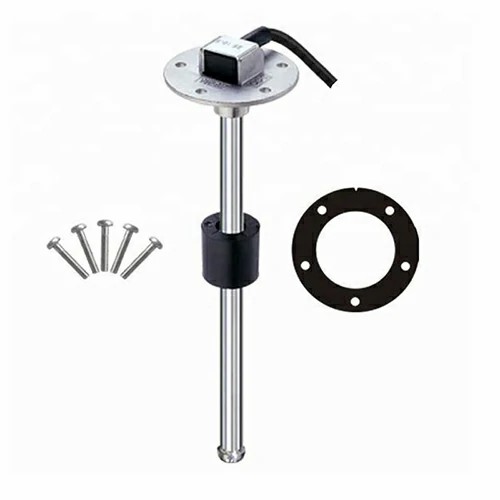
Installation instructions of fuel level sensor:
Step 1: open the fuel filler of the fuel tank, observe or test the approximate position of the sensor and internal diaphragm of the fuel tank with a wooden stick and branch.
Step 2: determine the position of the hole. The hole should be far away from the fuel filler, the sensor of the original vehicle and the internal diaphragm.
Step 3: drill a 10mm diameter hole on the mailbox with a 10mm drill bit.
Step 4: use iron wire to penetrate through the 10mm hole and out of the oil filler to guide the sensor.
Step 5: put the sensor into the oil tank from the oil filler, and clamp the wire harness end of the sensor with iron wire. It is important to ensure that the sensor does not fall off.
Step 6: apply diesel resistant sealant around the small hole to prevent oil leakage.
Step 7: screw on the big nut. If the sensor rotates with the nut at this time, fix the gap on the threaded rod at the top of the sensor with an open slotted screwdriver, and continue to tighten the screw with a 12 inch version.
Step 8: wiring the left one is the sensor's own harness. Brown is the sensor power supply, which is connected to the GPS host 5V (connected to the GPS brown line), black is the grounding connected to the negative pole of the GPS host (connected to the GPS black line), and blue is the fuel signal line (connected to the GPS purple line). On the right is the line extending from the GPS host to the sensor, which passes through the small hole on the side from the outside of the nut into the inside of the nut. Note: the extension wire is threaded from the outside to the inside through the hole. After internal wiring, reel the wire into the screw. After connecting the three joints, seal the small hole of the incoming line and the top of the sensor with 704 sealant, and then gently lift up the line and put it inside the nut.
Step 9: apply some sealant on the sealing part.
Step 10: tighten the cap so that it cannot be opened with bare hands.
Step 11: arrange the harness and complete the installation.

Get a Quote / Info