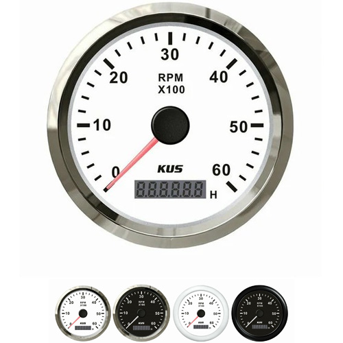
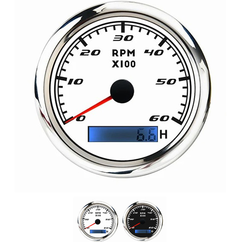
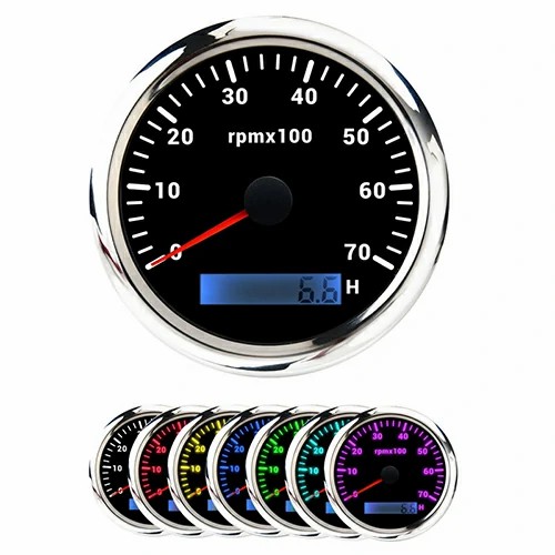
tachometer sensor diesel engine
The speed sensor on the engine is a Hall sensor, which works by the signal teeth on the flywheel and converts the magnetic signal into electrical signal through semiconductor components. This kind of sensor can work without contacting the measured object. The speed sensor on the transmission directly converts the mechanical signal into electrical signal. The sensor meshes with the main reduction gear of the transmission through the gear. The rotation of the main reduction gear drives the sensor gear to rotate, so as to output the speed signal. Through the principle of magnetoelectricity, when the trigger tooth rotates, the coil will sense the change of size and strength, and will sense the AC telex to the computer. I hope it can help you. One is mechanical, that is, the flywheel speed is directly connected to the meter with a flexible shaft, the pointer in the meter will swing according to the speed, and the swing value can be read on the dial. An electronic speed sensor on a flywheel converts the time interval of the induction signal into speed through software calculation. Then it is reflected in the form of pointer or number. Generally, there are two types of code disc (photoelectric effect) and Hall (magnetic effect). The principle is basically 1. The code disc is generally engraved with the part that sees light but does not see light on the disc, or with the gear (low precision), and then collected with the photoelectric switch. When the rotating code disc or the light blocking part on the gear disc becomes the part that does not block light, the photoelectric switch will respond to the output high and low levels. The frequency of the output level is directly proportional to the speed, and the measured frequency will measure the speed, The frequency can also be converted into a voltage or current signal. Another kind of Hall's is to add a magnet equally on the rotating body, and the sensor is fixed against the magnet. When rotating, the sensor and the magnet coincide and induce once, and the output pulse jumps. The faster the speed is, the higher the frequency output is. The frequency of the output level is directly proportional to the speed. The speed is measured when the frequency is measured, and the frequency can also be converted into voltage or current signal.
The engine speed sensor is an inductive sensor that obtains the engine speed and the accurate angular position of the crankshaft (input system). A separate signal wheel for the engine speed sensor is installed on the flywheel. The signal wheel is designed as a wheel with many tooth segments, which is divided into 60 tooth segments Whenever the signal rotates through the sensor, an AC voltage will be generated, and its frequency will change with the speed. Frequency is the speed In order to identify the position of the crankshaft, the pulley has a gap between the two tooth segments The engine speed sensor is used to identify the engine speed Together with the hall sensor, it identifies the ignition top dead center of cylinder 1 of the engine, so as to determine the injection time and ignition timing.
 English


Get a Quote / Info