 English
 3 wire fuel level gauge wiring
Fuel level gauge is a kind of liquid level instrument commonly used in tank farms. It can not only display on the spot, but also output through 4~20mA remote transmission signal, which is generally a two-wire system. This article can introduce a connection method, the positive pole of the fuel level gauge is connected to the 24V output terminal of the meter, the negative pole of the fuel level gauge is connected to the positive pole of the 4~20MA input end of the meter, and then the negative pole of the 4~20MA input end of the meter is connected to the negative pole of the 24V output end of the meter. Pick up. The above connection method can use the 24V output of the instrument as the power supply of the liquid level gauge. If it is a four-wire system, it will be easy for me. The positive and negative poles of the power supply of the liquid level gauge are connected to the positive and negative poles of the power supply. The positive and negative poles of 4~20MA are respectively connected to the positive and negative poles of the 4~20MA input terminal of the meter. If a safety barrier is used, the positive and negative input terminals of the 24 volts connected to the safety barrier power supply (24V power supply) correspond to the positive and negative terminals of the liquid level gauge, and the positive and negative terminals of the output terminal correspond to the positive and negative terminals of the instrument.
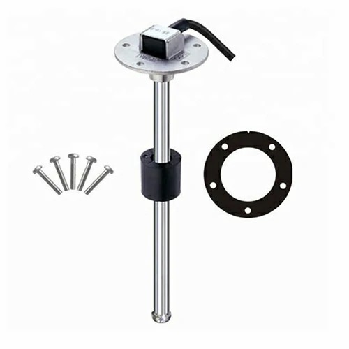
The meaning of the three wires of the fuel level switch is as follows:
1. The three wires are the fuel quantity signal line, the fuel gauge ground wire, and the low fuel quantity signal line;
2. The voltage of the fuel quantity sensing line changes with the change of the fuel quantity in the fuel tank;
3. The fuel gauge ground wire This ground wire is different from other ground wires. The original vehicle connects the instrument panel to the fuel tank sensor ground wire in order to accurately measure the fuel tank fuel volume. The resistance value between this line and the frame is 0 or approximately 0 (note: the multimeter should be measured at 200 ohms);
4. Low fuel sensor line When the fuel level is lower than the lowest point (warning point), the sensor switch is closed, and this line is connected to the ground line of the fuel gauge. The low fuel warning light on the instrument panel will be on, and the low fuel warning light will go out when the fuel level is higher than the lowest point (warning point).
There should be three wires at the end of the motor. Two of the main windings of the motor are connected to 220V mains, and the other auxiliary winding is connected to four capacitors. It means that the gear of the motor can realize the speed adjustment. According to the motor, there should be two gears, fast gear and slow gear. As shown in the picture, the red and blue wires of the main winding should be connected to two or two 0V mains red and yellow wires.

Get a Quote / Info