 English
 mechanical fuel level indicator gauge
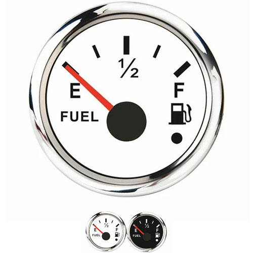
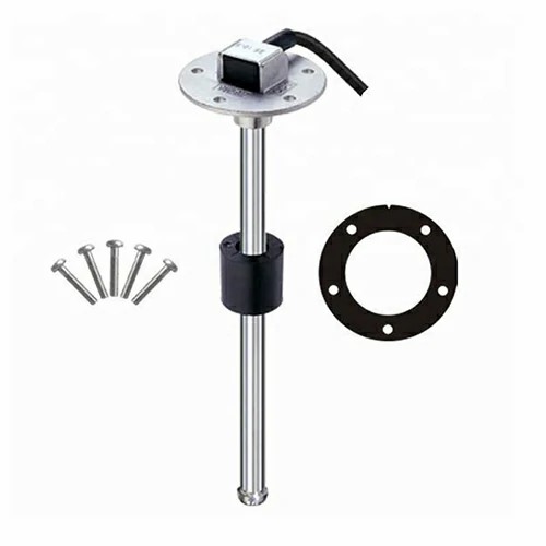
Mechanical car fuel level indicator
Although modern vehicles are designed with a fuel gauge indicating fuel consumption on the dashboard. But it usually uses an analog pointer display method marked with red marks, which is confusing and not very accurate. The fuel level indicator described in this article monitors the fuel tank at all times, notifies you with an LED indicator when the fuel level falls below a specified level, and emits an audible alarm when a dangerous level is approaching.
The fuel detection system consists of a floating sensor and an ammeter (fuel gauge) mounted on the fuel tank. The float-driven sensor is connected to a varistor inside the tank, which exhibits high resistance when the tank is empty and decreases when the tank is full. The fuel monitoring circuit works by detecting the voltage change across the fuel gauge and activating the buzzer before the fuel tank is almost empty. Point A of the circuit is connected to the inner terminal of the fuel tank, and point B is connected to the body.
The indicating circuit is composed of an operational amplifier chip CA3140 (IC1), two 555 timer chips (IC2 and IC3) and a decimal counter CD4017 (IC4). IC1 is connected to a voltage comparator, its inverting input terminal ② is connected to the reference voltage, and the non-inverting input terminal ③ is connected to the oil meter input terminal through R1 to extract the changing voltage. When the voltage of pin ③ is higher than the voltage of pin ②, the output of IC2 becomes high, making the green LED (LED1) light up, and this state is maintained until the voltage of pin ③ is lower than the voltage of pin ②. ③After the pin voltage becomes low, IC1 outputs from high to low, and sends a negative pulse through C1 to trigger the monostable circuit IC2. After IC2 is triggered, its output goes high and maintains a monostable time determined by R5 and C2, about 4 minutes.
The output of IC2 supplies power to relaxation oscillator IC3 through diode D2, whose oscillation is controlled by R6, R7, VR2 and C4. Calculated from the component values in the figure, the ON time during oscillation is 27 seconds and the OFF time is 18 seconds. The output pulse of IC3 is sent to the clock input pin (14) of IC4, and its output also becomes high one by one with the input pulse. When the circuit is on, LED1 and LED2 will light up if there is enough fuel in the vehicle's fuel tank. When the fuel is below the minimum fuel storage line, the output of IC1 becomes low, LED1 goes out, and the ② pin of IC2 receives a negative pulse, the output of IC2 becomes high and maintains for about 4 seconds, during this time, IC4 ( 14) The pin receives the clock pulse (from low to high) from the output of IC3.

Get a Quote / Info