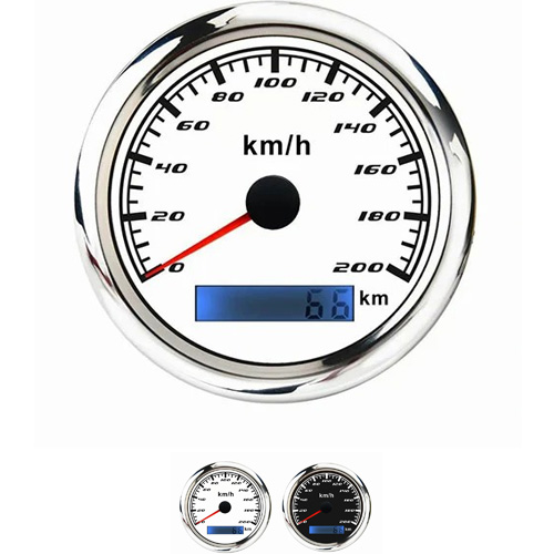
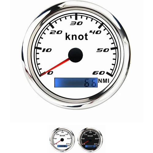
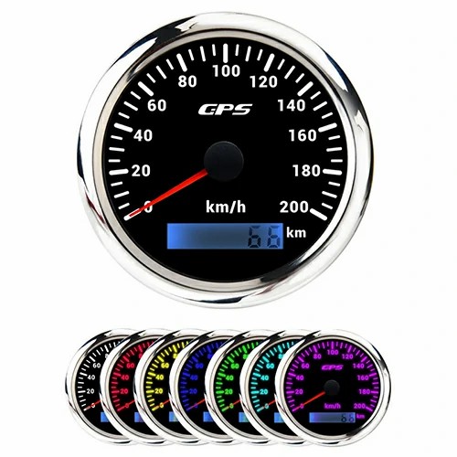
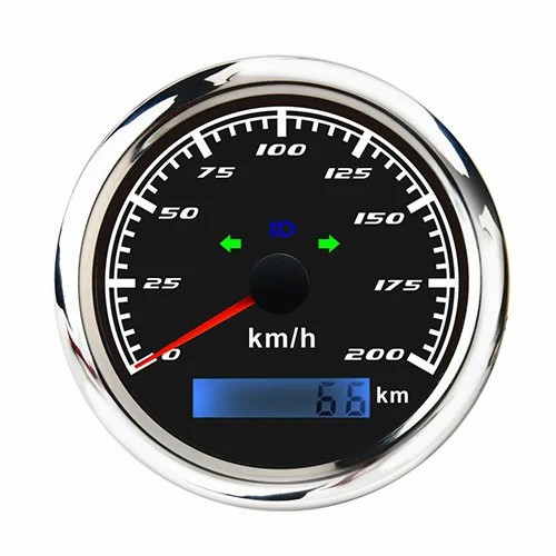
speedometer relocation bracket
The instrument panel of a car is a device that reflects the working conditions of each system of the vehicle. The installation of the panel requires a metal fixing bracket. The existing metal fixing bracket of the automobile instrument panel has the following deficiencies in use. The fixing ring is installed in the hole of the fixing ear, and the bolt passes through the fixing ring and is screwed into the car body, so as to realize when the metal fixing bracket is installed, when the fixing ring is installed in the through hole by the screw, it does not have a position-limiting effect, which reduces the installation efficiency of the fixing ring.
The purpose of this utility model is to provide a metal fixing bracket for an automobile instrument panel to solve the problem of installing a fixing ring in the perforation of the fixing ear proposed in the above-mentioned background technology. The bolts pass through the fixing ring and screw into the car body, thereby realizing the metal fixing bracket. During installation, when the fixing ring is installed in the through hole through the screw, it does not have the effect of limiting the position, which reduces the problem of the installation efficiency of the fixing ring. The utility model provides the following technical solutions: a metal fixing bracket for an automobile instrument panel, including a bracket body, a fixing ring, and screws. The outside of the bracket body is provided with fixing ears, and the surface of the fixing ears is provided with perforations. The fixing ring passes through The screw is installed in the perforation, the fixed ring and the perforation are provided with a limit mechanism, and the limit mechanism includes a limit block, an extension groove, a telescopic spring, and a limit groove, and the outside of the perforation is provided with symmetrically distributed extension grooves, One end of the limiting block is embedded in the extension groove, and the other end extends out of the extending groove. One end of the telescopic spring is connected to the embedded end face of the limiting block, and the other end is connected to the bottom of the extending groove. The fixed ring The outer wall is provided with symmetrically distributed limiting grooves, and the limiting blocks are engaged with the limiting grooves; a sliding assembly is arranged on the limiting blocks and the extending grooves.
Preferably, the sliding assembly includes sliding grooves and sliding blocks, symmetrically distributed sliding grooves are provided on the outer side of the extension groove, and sliding blocks sliding in the sliding grooves are arranged on the outer side of the embedded end of the limiting block. Screw holes are provided on the fixing ear and the fixing ring, and the screw holes correspond to each other. The limiting groove is an arc structure, and the inside of the bracket body is disassembled and provided with an instrument panel. A transparent cover is movably provided on the outside of the support body, and a stabilizing component is provided on the transparent cover and the support body. The stabilizing component includes a fixed column, a block, and a fixed groove. The movable end of the transparent cover is provided with symmetrically distributed fixed columns, and the corresponding end of the bracket body is provided with a fixed groove for the insertion of the fixed column, and the inner surface of the fixed groove An abutting block against the fixed post is provided.
 English

Get a Quote / Info