 English
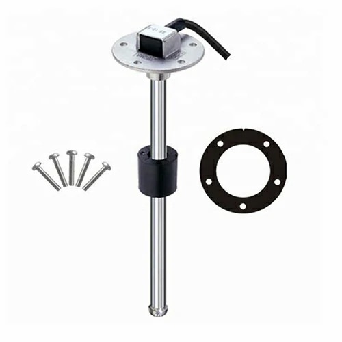
 fuel level sensor electrical
On the high-pressure pump at the inlet side of cylinder 4, the pressure regulating valve is above, the low-pressure sensor is in the middle, and the high-pressure sensor is below. The computer detects that the fuel pressure is low. What's more, the pressure of the gasoline pump is not enough. Check the comparison with the fuel pressure gauge. The data flow is the first in 103 groups, with about 5 normal values.
The car reports that there is an electrical fault in the fuel pressure sensor circuit that exceeds the upper limit, indicating that the low-pressure fuel supply pressure is insufficient. If your chassis oil pipe is OK, try replacing the fuel filter element first. If it is not good, you have to replace the oil pump.
There are three wires on the oil level / temperature sensor electrical, which are positive wire, ground wire and signal wire. The instrument outputs a high potential of about 11 V on the signal line, and the sensor controls the grounding to generate a pulse width modulated signal. The first part is the pulse signal that the sensor instantly heats the oil level sensor. The heating time depends on the oil temperature. The purpose of heating is to judge the oil level according to the sensor cooling time. After the sensor enters the cooling phase (Part 3), the cooling time is basically proportional to the oil level. The shorter the cooling time, the higher the oil level. The longer the cooling time, the lower the oil level. The judgment error of the oil level will not be greater than ± 3 mm. The cooling time is between 200 and 1000 ms. The oil temperature is directly measured by the sensor. The temperature signal is transmitted through the pulse signal (Part 2). The signal pulse width is between 25 ~ 85 Ms.
Through the analysis of the working principle, it can be seen that the cause of this fault may be caused by the following aspects: ① oil level / temperature sensor fault. ② Line fault. ③ Instrument panel fault. ④ Power supply or ground fault. The next thing to do is to eliminate each possible fault point one by one.
The author first unplugs the sensor plug from the sensor, then turns on the ignition switch and measures the three pins on the plug side. Among them, pin 1 is the positive power supply end. When the ignition switch is turned on, there should be battery voltage. Pin 2 is the grounding end, and pin 3 is the signal line of the instrument panel. When the ignition switch is turned on, the instrument panel sends a trigger signal of about 11 v. After measurement, there is no problem with the three pins, which eliminates the possibility of circuit, power supply and grounding failure.

Get a Quote / Info