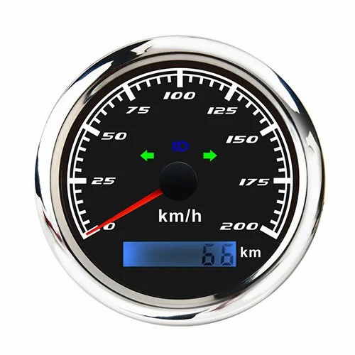
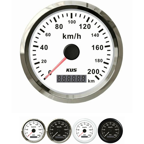
 English
 digital speedometer not working
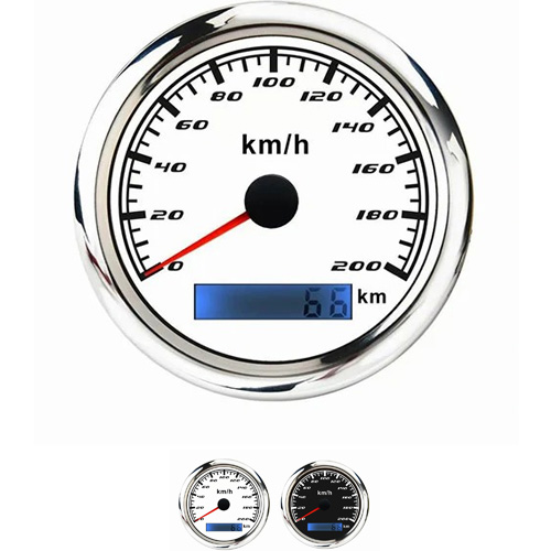
Fault judgment of digital speedometer not working. Unplug the connector of the transmitter and turn on the ignition switch. The No. 2 electrode connected with the red line on the brown bottom in the connector is extended with a self-made wire with plug, which makes a virtual scratch on the grounding part of the vehicle body and inputs pulse signal to the instrument.This phenomenon is caused by a problem with the speedometer sensor of the first vehicle. It is necessary to check whether the plug of the speedometer sensor is connected falsely? If there is no problem, replace with a new speed sensor. Second, some models do not have a separate speed sensor, which is integrated with the wheel speed sensor. In this case, you need to check whether there is a problem with the wheel speed sensor or the ABS pump in the brake system? Third, this phenomenon is caused by the problem of the vehicle instrument. Check whether the odometer displays normally? If the odometer displays normally, this is usually a problem with the instrument. It needs to be replaced or repaired. Practice has proved that the method of making pulse stop signal by virtual scratching of electric wire is effective to determine the location of the fault.
1. First, operate according to the above fault judgment method, pull out the sensor connector and draw the pulse signal line. At this time, the speedometer pointer does not rotate. Then, the instrument panel was removed and the wiring was measured. No problem was found. Then, carefully check the instrument panel to see if there is any abnormality. It is found that the grounding electrode of the speedometer is open. After re welding, the speedometer works normally.
2. The speedometer sometimes works and sometimes does not work: most of the lines have poor contact. The live wire and ground wire of the speedometer are shared with other instruments and indicators; The pulse signal line of the sensor passes through many connectors, and it is suspected that there may be poor contact when it passes through the connectors. The resistance of the pulse signal line between the instrument panel and the sensor connectors can be measured while shaking each connector by hand.
Get a Quote / Info